Table of Contents
Connector
A connector is used to connect two sub-systems. To be able to connect sub-systems they must have inputs and outputs defined.
The connector allows you to pair one or more outputs of a sub-system with inputs in another sub-system. When a block which is marked as an input is connected to an output it will take it’s values from the output block. In effect, it would be like replacing the id of the (input) block in all equations with the id of the output block.
When several outputs are connected to one input, their contributions are summed, as described in the example below.
Creating a connector
Connectors are created in the Matrix window, either manually by the user or automatically when sub-systems are added from the library.
To manually add a connector
- Right click on the off diagonal cell which is on the same row as the source sub-system and which is in the same column as the target sub-system. Select Connector from the the pop-up menu.
When the source sub-system is expanded, place the connector at the same row as the model output of the sub-system.
When the target sub-system is expanded, place the connector in the same column as the model input of the sub-system.
To manually add a connector in Graph window
- Move the mouse cursor to the label in the center of the source block. The block should now be outlined in green. Keep the left mouse button pressed, and move the mouse cursor to the target block.
Editing a connector
The block editor is shown by right-clicking the block in a window and selecting Edit (or double clicking). In the Blocks window, you can also show the block editor by selecting the block and clicking the  button, or by double-clicking the right-most “validation” column of the block.
The block editor has two tabs:
Values
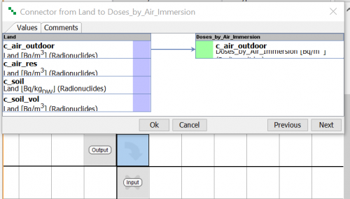
The table is used to pair model outputs with model inputs and has the following columns. For each output in the From (column on the left side) column an input can be selected in the To (column on the right side) column.
- From - List all the available model outputs of the source sub-system.
- Unit - Displays the unit of the output.
- Dimension - Displays the dimension of the output. The dimension of the output must be the same as the dimension of the input.
- To - List all the available model input can be selected.
- Unit - Displays the unit of the input.
- Dimension - Displays the dimension of the input.
- Message - If there is a problem with the connection, such as a dimension mismatch or a unit incompatibility.
In case of inputs and outputs do not allow auto connections, or names of relevant input and output are not the same, user needs to create connection in connector manually.
To create connection move the mouse cursor to the relevant output in the column on the left side. A green outline should be displayed. While keeping the left mouse button pressed, move the mouse cursor to the relevant input in the column on the right side. When you release the mouse button a connection should appear.
Comments
This tab is used during quality assurance process.
Example
Modules
A dose-response model is implemented as a modularized sub-system. The input to the dose-response module is the concentration. The concentration can be given either directly as a time-series, or it can be provided by another model.
The modeller creates a lookup table in the sub-system, named Concentration. This way a user can enter the concentration values directly.
To be able to connect the dose response module to other modules, a model input block is added to it’s sub-system and the Concentration lookup table is selected as an input.
A colleague of the modeller is an expert in atmospheric modelling and has created two modules, one for indoor air and one for outdoor air. The end-point for both of these modules is the concentration of a contaminant X. In the indoor module, the endpoint is is an expression named Concentration, and in the outdoor module there is a compartment named the same.
The Concentration blocks in both atmospheric modules have been marked as outputs by adding a model output in each module and selecting Concentration.
All the modules are put in the module library.
Connecting modules
An end-user can now quickly assemble a model for estimating the effect for a person breathing outside or indoor air by adding first an atmospheric module to an empty project, and then adding the dose response module. Because the modellers were careful when naming inputs and outputs, it is easy for the end-user to see which pieces go together. Actually, when adding a module from the library, Ecolego will automatically search the existing model for inputs/outputs with names that match those of the inputs/outputs of the new module and ask if the user want to connect them.
Multiple input connections
A typical scenario might be one where a person spends some time outdoors and some time indoors. One can also imagine other pathways, such as dermal exposure or exposure from ingestion. How can many multi-media modules be connected to the same dose response module?
There is no limitation on the number of connectors that connects to an input. When more than one output is connected to an input, the input receives the summed total of the outputs. This way several Concentration outputs can be connected to the Concentration input of the dose response module.


